Pull-down Resistor Circuit Schematic Klipps
Computer & Technology
· minn AdamStanislav
CC0 (Public Domain)
CC0 Domenju Pubbliku - b'xejn għall-użu personali u kummerċjali, l-ebda attribuzzjoni meħtieġa.
Att ta’ liċenzja →
Pull-down Resistor Circuit Schematic - AdamStanislav (CC0 (Public Domain)), via Clipart.Free
Il-kreditu huwa fakultattiv - CC0 ma jeħtieġ xejn.
Dwar din l-immaġni
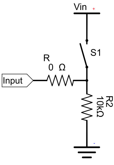
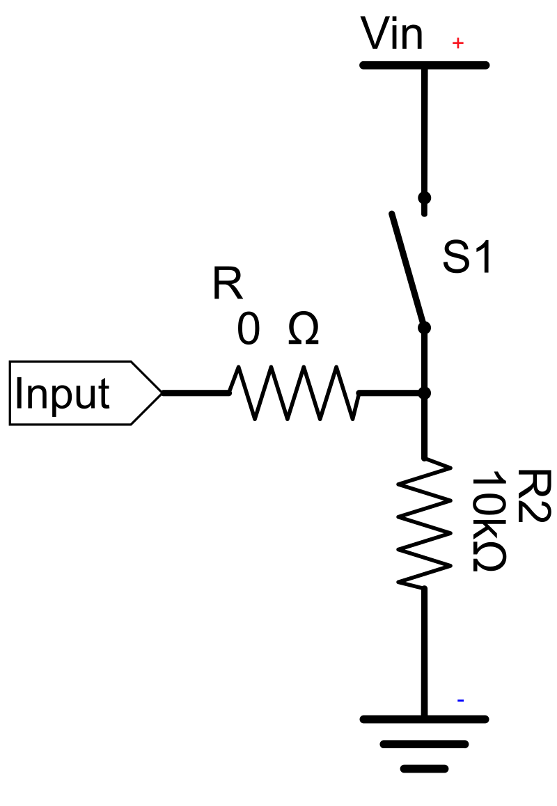
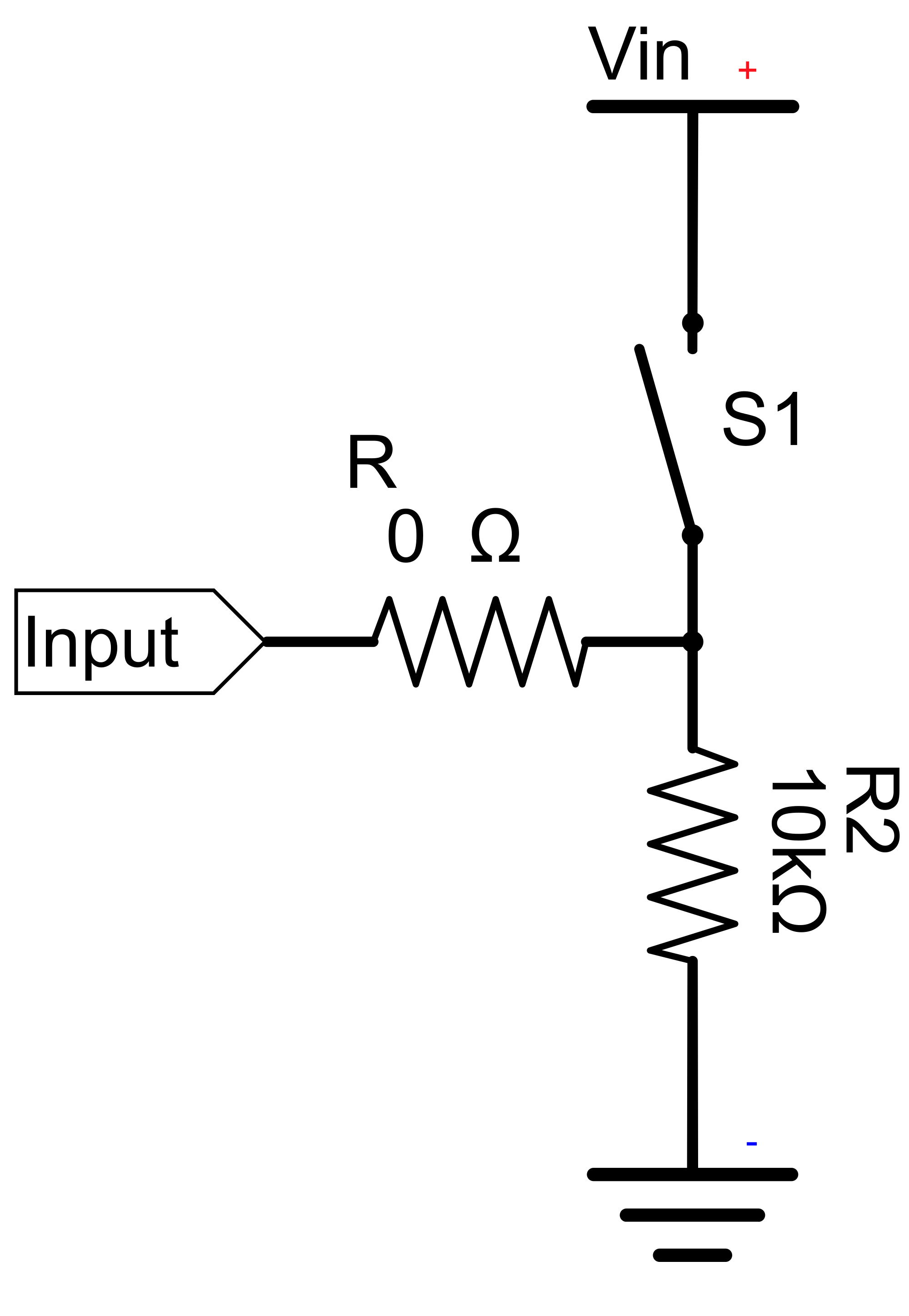
If the switch S1 is closed, electricity takes the path of the least resistance and flows from the positive terminal Vin through the 100Ω resistor R1 to the Input pin. If the switch is open, the Input pin is connected to the ground through the two resistors R1 and R2, so no electricity is floating toward the Input pin, as it would without the 10kΩ pull-down resistor R2, at least for some time afte…
| Dimensjonijiet | 615 × 890 px (SVG - scales to any size) |
|---|---|
| Daqs tal-fajl | 24.4 KB SVG · PNG 400/800/2000 px |
| Liċenzja | CC0 (Public Domain) · Spjegazzjoni tal-liċenzji Clipart |
| Artist | AdamStanislav |
| Sors | Openclipart · Paġna oriġinali → |
It-tikketti
Neħtieġu li jikkonvertu jew jeditjaw dan?
Dawwar l-SVG f'PDF, ICO jew WebP - jew ibdel id-daqs tal-PNG - b'konvertituri onlajn b'xejn.
Konvertituri tal-fajl ħielsa →Tibni app?
Niżżel din l-immaġni (u l-librerija kollha) bħala JSON b'API key b'xejn - 500 talba/jum.
Dokumenti tal-API Clipart →
Imħabba Clipart.Free? Aqsamha ma' ħaddieħor
Mistoqsijiet li jsiru ta' spiss
Iva. "Pull-down Resistor Circuit Schematic" huwa dedikat għad-dominju pubbliku taħt CC0 1.0 - l-artist irrinunzja d-drittijiet tal-awtur kollha. Tista' tniżżlu, timmodifika, tipprintja u terġa' tippubblikah għal kwalunkwe skop, personali jew kummerċjali, mingħajr ma tistaqsi lil ħadd.
Iva. CC0 (Public Domain) xogħol tal-arti ma jeħtieġ l-ebda attribuzzjoni u l-ebda tariffa, anke f'xogħol kummerċjali - prodotti, proġetti tal-klijenti, apps, ippakkjar u stampar. Kreditu huwa apprezzat iżda qatt ma huwa meħtieġ.
Il-fajl prinċipali huwa 615x890 px SVG vector (24.4 KB) li jista' jiżdied għal kull daqs mingħajr telf ta' kwalità.PNGs trasparenti lesti huma disponibbli b'wisa' ta' 400, 800 u 2000 pixel - mingħajr reġistrazzjoni, mingħajr watermark.
"Pull-down Resistor Circuit Schematic" ġiet imfassla minn AdamStanislav u kondiviża fuq Openclipart taħt dedizzjoni tad-dominju pubbliku.Il-paġna tas-sors hija marbuta fid-dettalji ta' hawn fuq - il-kreditu tal-artist huwa fakultattiv iżda ġest sabiħ.
"Pull-down Resistor Circuit Schematic" turi dokumentazzjoni, tutorji, gverti tal-bidu u skrins tal-app onboarding - u CC0 tfisser li tista' tinġarr ġewwa l-prodott innifsu.
Niżżel l-SVG u tiftaħha f'editur b'xejn bħal Inkscape (desktop) jew għodda tal-browser - jew waħħalha direttament fil-Figma bil-buttuna Ikkopja SVG.Kull forma u kulur huwa editjabbli, u l-verżjoni modifikata tiegħek hija tiegħek biex iżżomm jew tbiegħ.