Pull-down Resistor Circuit Schematic Àwọn àwòrán
Computer & Technology
· nípa AdamStanislav
⬇ Àwọn ààyè-iṣẹ́
✓ Àwọn ìṣàmúlò-ètò àìfihàn - kò si àgbéwọlé, kò si àmì-ìwé
CC0 (Public Domain)
CC0 Public Domain - ọ̀fẹ̀ fún ìlòjútó àwọn ìṣàmúlò-ètò aládàrà àti àwọn ìṣàmúlò-ètò ọ̀fẹ́, kò ní àwọn ìṣàmúlò-ètò tí a fẹ́.
Àwọn ìṣẹ̀dà ìṣẹ̀dà →
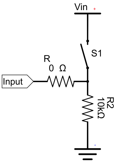
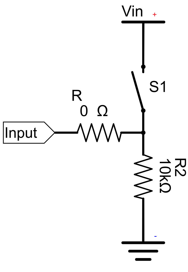
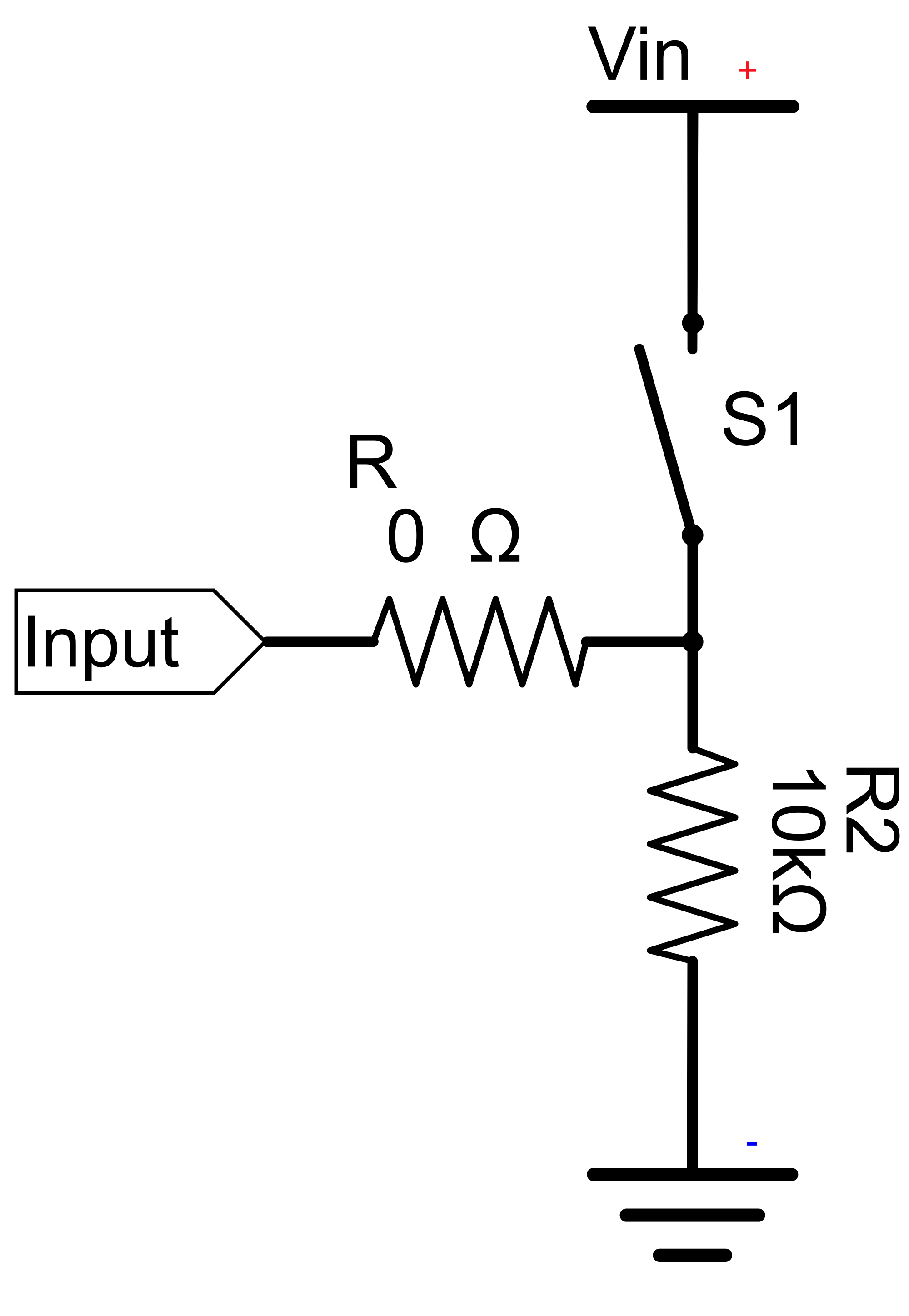
Pull-down Resistor Circuit Schematic - AdamStanislav (CC0 (Public Domain)), via Clipart.Free
Àwọn ìṣàmúlò-ètò jẹ́ àwọn ìṣàmúlò-ètò tí a fẹ́ - CC0 kò ní ìṣàmúlò-ètò kan.
Àtòjọ-ẹ̀yàn yìí
If the switch S1 is closed, electricity takes the path of the least resistance and flows from the positive terminal Vin through the 100Ω resistor R1 to the Input pin. If the switch is open, the Input pin is connected to the ground through the two resistors R1 and R2, so no electricity is floating toward the Input pin, as it would without the 10kΩ pull-down resistor R2, at least for some time afte…
| Àwọn ìṣàmúlò-ètò | 615 × 890 px (SVG - scales to any size) |
|---|---|
| Ìwọ̀n Fáìlì | 24.4 KB SVG · PNG 400/800/2000 px |
| Àwọn Àmì-ìwé | CC0 (Public Domain) · Àwọn ìwé-ẹ̀rí àwọn ìṣẹ̀dà àwọn |
| Àwọn Àkọ́kọ́ | AdamStanislav |
| Àwọn Ìṣàmúlò-ètò | Openclipart · Àwọn ojú-ìwé ìṣàmúlò-ètò → |
Àwọn Àmì-ìwé
Ǹtí o fẹ́ láti yipada àtí látì yipadà yìí?
Yí SVG padà sí PDF, ICO tàbí WebP - tàbí ìṣàfarawé PNG - láti àwọn ìṣàmúlò-ètò àìfẹ́ lórí intanẹ́ẹ̀tì.
Àwọn ìṣàmúlò-ètò àìfihàn →Ṣẹ̀dá ìṣàmúlò-ètò?
Gba àwòrán yìí (ati àwọn láìṣè gbogbó ní pàtó) bí àwọn JSON láti inú bọ́tìnì API ọ̀fẹ́ - àwọn ìṣàmúlò-ètò 500/ọ̀jọ.
Àwọn Àkọsílẹ̀ API →Àwọn Àtòjọ-ẹ̀yàn
Ya. "Pull-down Resistor Circuit Schematic" tí a fi pamọ́ sí àwọn ààyè-iṣẹ́ ìtàn lórí CC0 1.0 - àwọn awáròyìn náà tí wọ́n pàtó àwọn ẹ̀yàn àìdálẹ̀. O lè gbàwọlé, yíṣẹ̀, píríǹtì àti ìṣàfihàn rẹ̀ láti sé àwọn ààyè-iṣẹ́ fún ẹnikẹ́ni, fún ara rẹ̀ tàbí fún iṣowo, látí kò bá ẹnikẹni beerè.
Yes. CC0 (Public Domain) artwork requires no attribution and no fee, even in commercial work - products, client projects, apps, packaging and print. A credit is appreciated but never required.
The master file is a 615x890 px SVG vector (24.4 KB) that scales to any size without quality loss. Ready-made transparent PNGs are available at 400, 800 and 2000 pixels wide - no signup, no watermark.
"Pull-down Resistor Circuit Schematic" was drawn by AdamStanislav and shared on Openclipart under a public-domain dedication. The source page is linked in the details above - crediting the artist is optional but a nice gesture.
"Pull-down Resistor Circuit Schematic" illustrates documentation, tutorials, startup decks and app onboarding screens - and CC0 means it can ship inside the product itself.
Ṣàfihàn SVG náà láti ṣí nínú àwọn ààtò àìṣàfilọ́lẹ̀ ọ̀fẹ́ bíi Inkscape (desktop) tàbí àtòjọ-ẹ̀yàn àìṣàfilọ́lẹ̀ - tàbí fi pamọ́ sínú Figma láti inú bọ́tìnì Ṣẹ̀dá SVG. Àwọn ìṣàmúlò-ètò àti àwọ̀ gbogbò ní àtòjọ-ẹ̀yàn, àti ìṣàfilọ́lẹ̀ rẹ̀ ní ẹ̀yàn rẹ̀ láti pàtó àti láti sàlú.